Introduction
Architecture drawing — also known as architectural drafting or architectural representation — is the technical and artistic practice of communicating building designs through precise two-dimensional and three-dimensional graphics. It is the universal language of the built environment, enabling architects, engineers, contractors, and clients to share, refine, and execute design ideas.
Unlike freehand sketching or fine art, architectural drawing follows a strict system of conventions: standardised scales, symbols, line weights, and projection methods that make drawings legible across borders and disciplines. A floor plan drawn in Lagos should be as readable to a contractor in London as it is to one in Tokyo.
At its core, architectural drawing serves three purposes: exploration (generating and testing ideas), communication (sharing intent with collaborators and clients), and documentation (providing construction-ready information to builders).
“Architecture begins with a pencil on paper — it is the first act of building.”
Table of Contents
- What is architecture drawing?
- Types of architectural drawings
- Essential tools and materials
- How to read architectural drawings
- Step-by-step guide to architectural drawing
- Digital vs. hand drawing
- Scale, symbols, and conventions
- Career applications
- Frequently asked questions
1. What is Architecture Drawing?
Architecture drawing is the practice of visually communicating building designs through a system of standardised technical graphics. It bridges the gap between an architect’s creative vision and the physical reality of a constructed building.
Every architectural project — from a single-room extension to a 50-storey skyscraper — begins and ends with drawings. At the concept stage, drawings are exploratory tools for thinking. At the construction stage, they are legal contractual documents that builders follow to the millimetre.
Architectural drawing encompasses a wide range of media and techniques: pencil sketches on tracing paper, ink on drafting film, and digital drawings produced in AutoCAD, Revit, or ArchiCAD. Regardless of medium, the underlying principles of scale, projection, and convention remain the same.
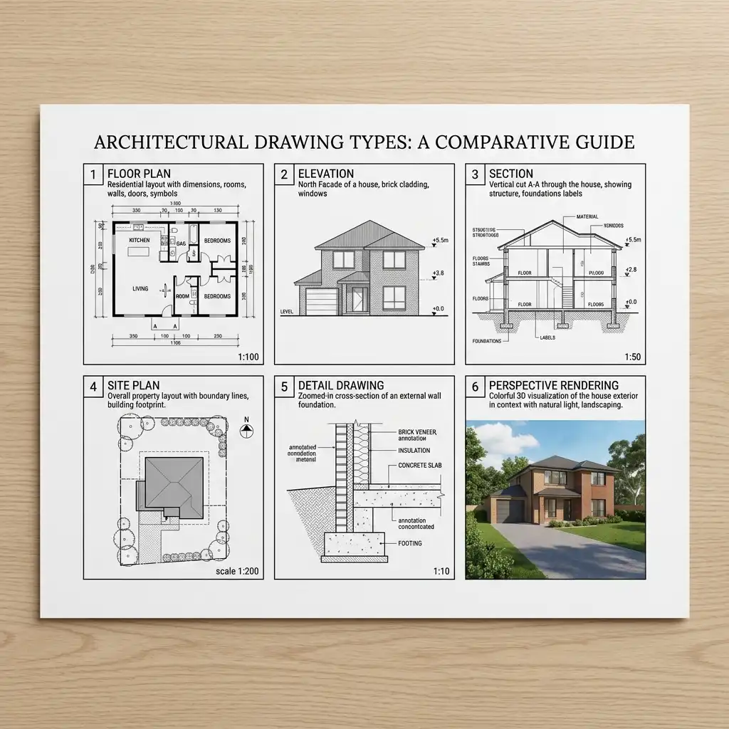
2. Types of Architectural Drawings
Professional architectural practice relies on a family of drawing types, each conveying specific spatial and technical information. Understanding each type is fundamental to reading and producing architectural documents.
Floor Plan
A horizontal cut through the building at approximately 1 metre above floor level, showing room layout, wall thicknesses, door and window positions, and fixed elements such as stairs, bathroom fittings, and kitchen units. The floor plan is the most important and most frequently used drawing type in architecture.
Elevation
A flat, orthographic view of a building’s exterior facade. A complete set of elevations typically includes North, South, East, and West-facing views. Elevations show the building’s height, window and door proportions, material finishes, and relationship to ground level.
Section
A vertical cut through the building that reveals internal heights, floor-to-floor distances, ceiling levels, structural elements, and the relationship between spaces stacked vertically. Sections are often the most technically demanding drawings to produce and the most revealing of design quality.
Site Plan
An aerial view of the entire site showing the building footprint, site boundaries, roads and paths, parking, landscaping, drainage, and the relationship to neighbouring buildings and streets. Site plans are typically drawn at 1:200, 1:500, or 1:1000.
Detail Drawing
Large-scale views — typically 1:5 or 1:10 — of complex construction junctions such as window sills, roof eaves, stair nosings, and waterproofing interfaces. Detail drawings are what contractors refer to when assembling precise building components.
Perspective and 3D Drawings
Realistic or axonometric three-dimensional views that communicate spatial quality, massing, and material character to non-technical clients and planning authorities. These range from hand-drawn perspectives to photorealistic computer renderings.
Concept Sketches
Rapid, gestural diagrams produced early in the design process to explore ideas. These are intentionally loose — the goal is speed and creativity, not accuracy. A skilled architect can communicate an entire design strategy in a 30-second sketch.
Construction Drawings (Working Drawings)
The complete set of legal, contractual documents used to construct a building. These include fully dimensioned floor plans, elevations, sections, structural drawings, and specifications. They must comply with local building regulations and are submitted for planning permission and building control approval.
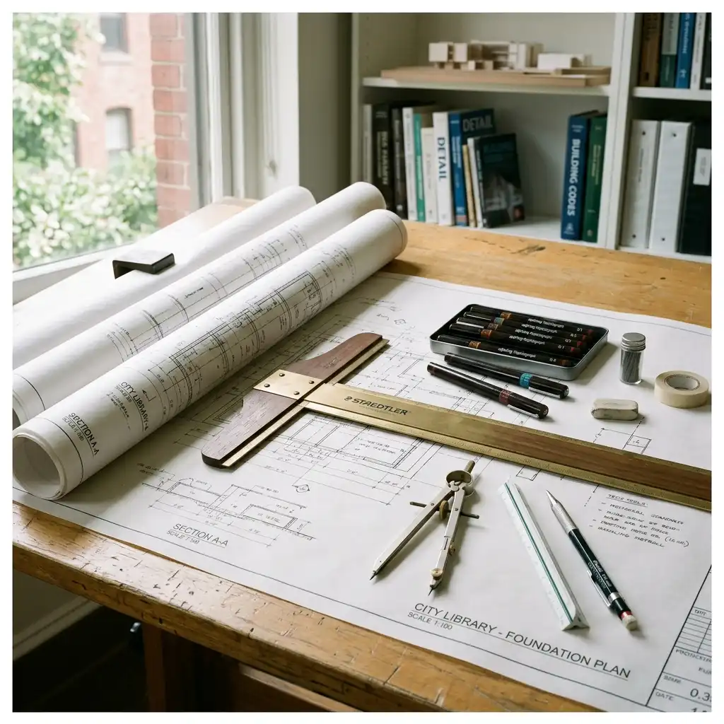
3. Essential Tools and Materials
Whether you draw by hand or on a computer, mastering your tools is as important as understanding drawing conventions.
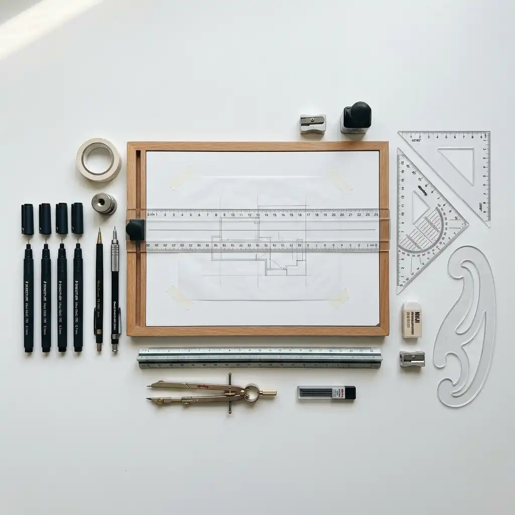
Traditional Hand Drawing Tools
Technical pen set (0.13–0.8mm) — Rotring Rapidograph or Staedtler Mars are industry standards. Different nib sizes correspond to different line weights: 0.13mm for dimension lines, 0.35mm for visible edges, 0.5–0.7mm for cut lines.
Set squares — A 30/60° and a 45° set square allow you to draw parallel and perpendicular lines at standard angles.
Parallel motion or T-square — Mounted to the drafting board, these ensure true horizontal lines across the full width of the drawing.
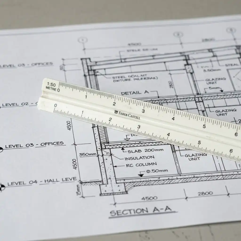
Architect’s scale rule — A three-sided rule with scales at multiple ratios (1:100, 1:50, 1:20, etc.). Essential for measuring drawings accurately without calculation.
Drafting board — An A1 or A0 board with a true flat surface and a parallel motion bar.
Tracing paper and cartridge paper — Tracing paper allows you to overlay and iterate on designs. Cartridge paper is used for final ink drawings.
French curves and flexi-curve — For drawing smooth curved lines that cannot be produced with a compass.
Compass and dividers — For drawing arcs and transferring measurements.
Digital Drawing Tools
AutoCAD — The industry-standard software for 2D architectural drafting, widely used for construction documentation worldwide.
Revit — Autodesk’s Building Information Modelling (BIM) platform, used for large and complex projects requiring coordination between architectural, structural, and MEP disciplines.
ArchiCAD — An architect-focused BIM application widely used in Europe and Australia, known for its intuitive interface.
SketchUp — Popular for quick 3D massing and concept modelling. Used extensively in early design stages.
Rhino + Grasshopper — The preferred platform for parametric design and complex geometries. Essential in high-end contemporary practice.
Procreate / Adobe Fresco — Digital sketching tools for iPad, popular for concept development and presentation drawings with a natural stylus feel.
4. How to Read Architectural Drawings
Before you can produce architectural drawings, you must be able to read them fluently. Here are the key skills every architect and construction professional develops.
Understanding Scale
All architectural drawings are produced at a ratio scale. Common scales include 1:100 (site and floor plans), 1:50 (room layouts and elevations), 1:20 (stair and kitchen details), and 1:5 (material junctions). A scale of 1:100 means every 1mm on the drawing represents 100mm (0.1m) in reality.
Reading Line Weights
Line thickness communicates importance and spatial depth. Cut lines — walls and slabs cut through on plans and sections — are the thickest (0.5–0.7mm). Visible edges beyond the cut are medium weight (0.25–0.35mm). Dimension and annotation lines are the finest (0.13–0.18mm). Consistent line weight discipline is one of the most recognisable markers of professional drawings.
Symbols and Conventions
Architectural drawings use internationally recognised symbols: a quarter-circle arc for door swings, hatching patterns for materials (diagonal lines for concrete, stretcher bond for brickwork), north point arrows on plans, section cut arrows indicating cut direction, and grid reference systems (A, B, C / 01, 02, 03) to coordinate between sheets.
Title Block and Drawing Information
Every drawing sheet carries a title block containing the project name, client name, drawing title, drawing number, scale bar, revision number, date, and the name of the practice. Always check the title block first when reading an unfamiliar drawing.
5. Step-by-Step Guide to Architectural Drawing
Whether you are drawing a simple room or a complex building, the workflow follows a consistent sequence.
Step 01 — Understand the brief Before drawing, clarify the project: site dimensions, programme requirements, client needs, local planning regulations, and budget. Drawings that begin without this foundation waste significant time.
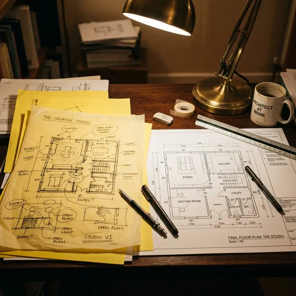
Step 02 — Sketch concept diagrams Use freehand bubble diagrams and massing sketches to explore spatial relationships. Work at small scale (1:500 or smaller) with thick markers or soft pencils. Do not worry about accuracy — generate as many options as possible.
Step 03 — Establish the site plan Once a concept direction is chosen, draw (or import in CAD) the site boundary, contours, north point, existing structures, and surrounding context. Position the building footprint within this.
Step 04 — Draft the floor plan(s) Starting at 1:100, draw walls, openings (doors and windows), and fixed elements (stairs, bathrooms, kitchen). Add structural grid lines, dimension strings, and room labels. Cross-reference with the section as you work to maintain vertical consistency.
Step 05 — Project the elevations Project horizontal lines from the floor plan to generate the elevation outlines. Add vertical heights taken from the section. Elevations should always be drawn simultaneously with sections to avoid dimensional inconsistencies.
Step 06 — Draw the sections Cut through the building at the most informative locations — typically through the main stair, a primary living space, and any split levels or roof complexity. Show floor build-ups, ceiling heights, and structural elements.
Step 07 — Develop construction details Enlarge critical junctions to 1:20 or 1:5. Detail the roof edge, window reveals, stair nosings, and waterproofing layers. These are the drawings contractors build from.
Step 08 — Annotate and title block Add material keynotes, specification references, dimension strings, and levels. Complete every sheet with a title block: project name, drawing title, drawing number, scale, revision, and date.
6. Digital vs. Hand Drawing: Which is Better?
This is one of the most debated questions in architectural education. The answer is both — at different stages of the process.
Hand drawing develops spatial literacy, proportional sensitivity, and design intuition in ways that digital tools do not. Many of the world’s most celebrated architects — Zaha Hadid, Álvaro Siza, Frank Gehry — were known for their expressive hand drawings. Many European and Latin American architecture schools continue to emphasise hand drafting in early years of study for precisely this reason.
Digital drawing is faster, more accurate, infinitely editable, and enables real-time coordination with structural and MEP engineers through linked BIM models. In professional practice, virtually all construction documentation is produced digitally.
The optimal approach: sketch by hand, produce by computer. Use pencil and paper to think, then move to CAD or BIM to document and detail. Architects who skip hand drawing entirely often struggle with spatial design thinking. Those who refuse digital tools are at a significant professional disadvantage.
7. Scale, Symbols, and Drawing Conventions
Mastering architectural conventions is what separates a technical drawing from a decoration.
The Architect’s Scale Rule
A scale rule is a three-sided rod with scales marked at different ratios. Common metric scales include 1:1, 1:5, 1:10, 1:20, 1:50, 1:100, 1:200, 1:500, and 1:1250. Imperial scale rules (used in the US) show 3″=1′-0″, 1/4″=1′-0″, 1/8″=1′-0″ and more. Knowing how to use a scale rule quickly and accurately is a non-negotiable professional skill.
Hatch Patterns and Material Symbols
Cut elements on sections and plans are identified by hatch patterns: diagonal lines for in-situ concrete, a stretcher bond pattern for brickwork, crossed diagonals for insulation, and small dots for compacted earth or hardcore. Visible (uncut) surface materials show a simplified representation of the actual material texture or finish.
Drawing Numbering and Sheet Management
Large projects may produce hundreds of drawing sheets. A robust numbering system is essential. Drawings are coded by discipline (A = architectural, S = structural, M = mechanical) and type (1xx = site plans, 2xx = floor plans, 3xx = elevations, 4xx = sections, 5xx = details). Revision clouds and revision triangles track all changes to issued drawings.
8. Career Applications of Architectural Drawing
Proficiency in architectural drawing is a gateway to multiple careers across the built environment.
Licensed Architect — The core professional role, requiring an accredited degree and professional licensure. Drawing is central to all stages of practice from concept design through to construction administration.
Architectural Technologist — Specialists in technical production drawings and building performance. Highly skilled in CAD and BIM documentation, construction details, and building specifications.
Interior Designer — Produces interior fit-out drawings, furniture layout plans, reflected ceiling plans, and finish schedules. Requires strong floor plan drawing skills and 3D visualisation ability.
Urban Designer / Urban Planner — Works at the scale of cities and neighbourhoods, producing masterplan drawings, zoning diagrams, transport infrastructure maps, and public realm plans.
Architectural Visualiser — Specialises in producing high-quality 3D renders and animations from architectural drawings for client presentations and marketing. Requires skills in Revit, Rhino, Enscape, Lumion, or V-Ray.
Construction Manager / Quantity Surveyor — Reads and interprets architectural and structural drawings to manage projects on site, estimate costs, and resolve technical queries during construction.

9. Frequently Asked Questions
Do I need to study architecture to learn architectural drawing? No — while a formal architecture degree provides the most structured training, architectural drawing skills can be self-taught or learned through technical colleges, online courses (Coursera, LinkedIn Learning, Udemy), and consistent daily practice. Many skilled drafters and CAD technicians do not hold architecture degrees.
What software is most in demand for architectural drawing? AutoCAD and Revit (both by Autodesk) are the most widely demanded globally. ArchiCAD is popular in Europe and Australia. SketchUp is widely used for early-stage 3D massing. Rhino with Grasshopper is increasingly required for parametric and complex-geometry projects.
How long does it take to learn architectural drawing? Basic proficiency in reading drawings can be developed in a few weeks of focused study. Producing professional-quality hand drawings typically takes 1–2 years of regular practice. AutoCAD proficiency can be achieved in 3–6 months of consistent use. Full BIM competence in Revit or ArchiCAD generally takes 1–2 years of project experience.
What is the difference between a floor plan and a layout plan? A floor plan is a technical architectural drawing showing walls, openings, dimensions, and structural elements at a specific building level. A layout plan shows how furniture and equipment are arranged within that floor plan — typically used for interior design presentations and space planning.
Can I use AI tools to generate architectural drawings? AI image generation tools such as Midjourney, Stable Diffusion, and DALL·E can produce compelling architectural concept visuals from text prompts — useful for early-stage client presentations. However, they cannot produce technically accurate, dimensioned construction drawings. For production-ready documentation, CAD and BIM software remains essential. AI tools are increasingly integrated into these workflows as co-pilot assistants rather than replacements.
Architecture drawing is one of humanity’s oldest and most refined systems of visual communication. Whether you are picking up a pencil for the first time or moving from hand drafting to BIM, the principles remain the same: clarity, precision, and the ability to make the invisible visible. Start with a single drawing today.