Architecture sketches are the raw language of design. Before a building is built, before the floor plans are digitised, before the materials are specified, there is the sketch — quick, expressive, and full of possibility. Unlike polished renderings, sketches capture the thinking process: the study of light, the play of mass and void, the relationship between a building and its site.
Whether you are an architecture student building your portfolio, a homeowner communicating with your architect, or simply someone who loves the beauty of hand-drawn lines, these 12 different architecture sketch types cover every essential category. Each sketch serves a different purpose, from conceptual exploration to construction documentation. Let’s get into it.
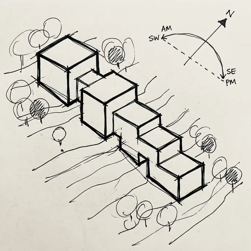
1. Conceptual Massing Sketch
The conceptual massing sketch is the very first mark on paper. It ignores windows, doors, materials, and details entirely. Instead, it focuses on pure form: how the building sits on the site, its rough proportions, and its relationship to sun, street, and landscape.
These sketches are intentionally loose and quick — often drawn in under a minute. Architects use them to test dozens of ideas rapidly, exploring how a long horizontal form feels compared to a vertical tower, or how a courtyard building might capture morning light. The best massing sketches use heavy line weights for the main volumes and lighter marks for context like trees or neighbouring buildings.
Quick Tips
- Use a chisel-tip marker for bold, expressive strokes that cannot be overworked.
- Draw the site boundary first, then fit the building inside it.
- Include a north arrow and a simple sun diagram.
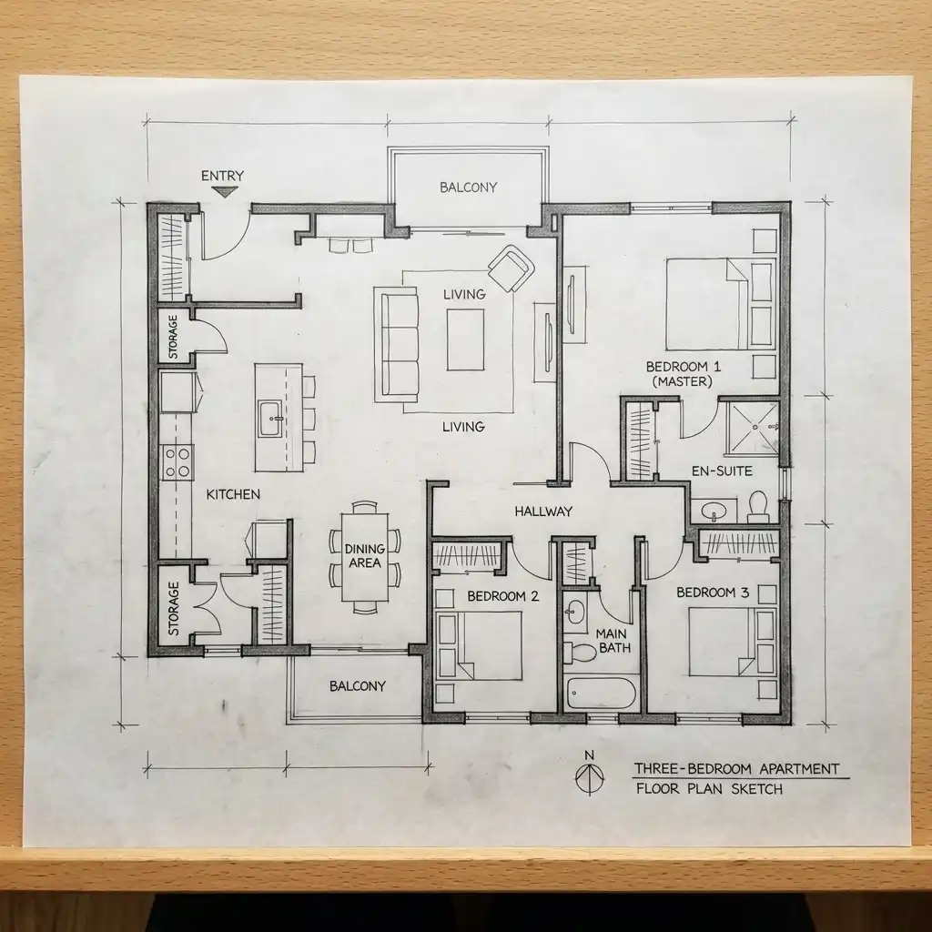
2. Floor Plan Sketch
The floor plan sketch is a bird’s-eye view of a building cut horizontally at approximately 120cm above floor level. It shows wall thicknesses, room layouts, door swings, window positions, stair locations, and the circulation paths that connect spaces. Unlike a conceptual sketch, the floor plan requires accuracy: walls must be parallel, rooms must be dimensionally consistent, and door swings must not block each other.
Architects use floor plan sketches to test spatial arrangements before committing to digital drafting. A typical hand-drawn floor plan sketch uses different line weights: thick lines for cut walls, medium lines for floor edges, and thin lines for furniture or dimension strings.
Quick Tips
- Use a hard pencil (2H or 3H) for initial layout, then trace with a darker pencil (HB or 2B) for final lines.
- Draw all walls at consistent thickness — 15cm for interior walls, 30cm for exterior walls.
- Indicate door swings with quarter-circles and window openings with parallel lines.
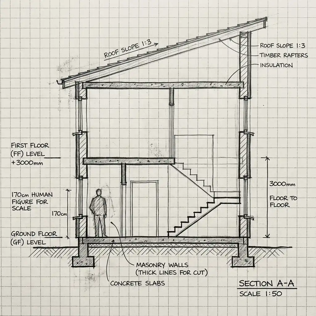
3. Section Sketch
A section sketch cuts vertically through a building to reveal what is inside. It shows floor-to-ceiling heights, roof slopes, foundation depths, and the relationship between different levels. While floor plans show how spaces connect horizontally, sections show how they stack vertically.
The most valuable section sketches include a human figure to provide scale. A typical section might cut through a living room with a double-height ceiling, showing the stair rising alongside, a window spanning both levels, and a skylight above. Line weights follow the same logic as floor plans: thick lines for cut elements (walls, floors, roof), medium lines for visible surfaces beyond the cut, and thin lines for details.
Quick Tips
- Draw the ground line first, then establish floor levels at consistent heights (typically 270cm for residential).
- Include a standing human figure at 170cm tall to show scale.
- Indicate the direction of the section cut on a corresponding floor plan.
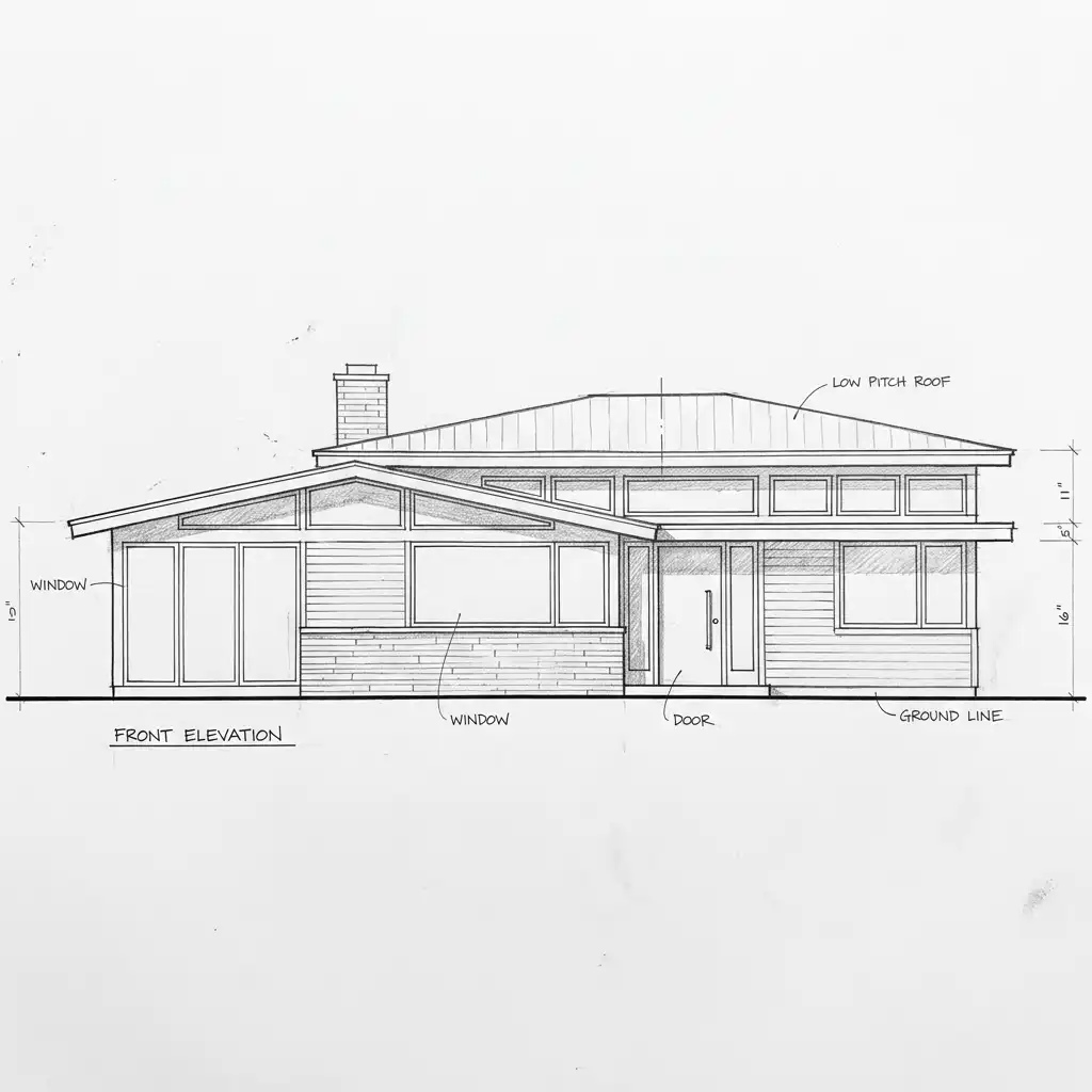
4. Elevation Sketch
An elevation sketch shows a building from the front, side, or rear — flat, without perspective distortion. It is the architect’s tool for studying proportions, window patterns, material transitions, and how the building meets the ground.
Unlike perspectives, elevations are drawn to scale but without depth. A front elevation sketch might show a house with a centred front door, windows arranged symmetrically, a roof ridge at the midpoint, and a chimney rising on one side. Architects use elevation sketches to test how different cladding materials (brick, wood, stone) might break across the facade.
Quick Tips
- Establish a consistent ground line across the entire drawing.
- Use dashed lines to indicate elements behind the facade, like a second-floor window aligned above a first-floor door.
- Shade one side of the elevation to suggest light direction.
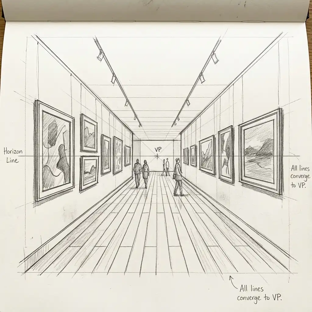
5. Perspective Sketch (One-Point)
The one-point perspective sketch creates the illusion of depth by converging all parallel lines to a single vanishing point on the horizon. It is ideal for showing interior spaces or building facades viewed straight-on, such as looking down a long corridor or approaching a building entrance.
To draw a one-point perspective, first establish the horizon line (at eye level, typically 150cm above ground) and place the vanishing point at its centre. All lines moving away from the viewer — wall edges, floor lines, ceiling lines — converge at this point. Vertical and horizontal lines remain straight. This sketch type helps clients understand how a space will feel when they stand inside it.
Quick Tips
- Place the vanishing point slightly off-centre for more dynamic compositions.
- Use a ruler for the initial construction lines, then freehand the final drawing.
- Add simple furniture or figures to establish scale.
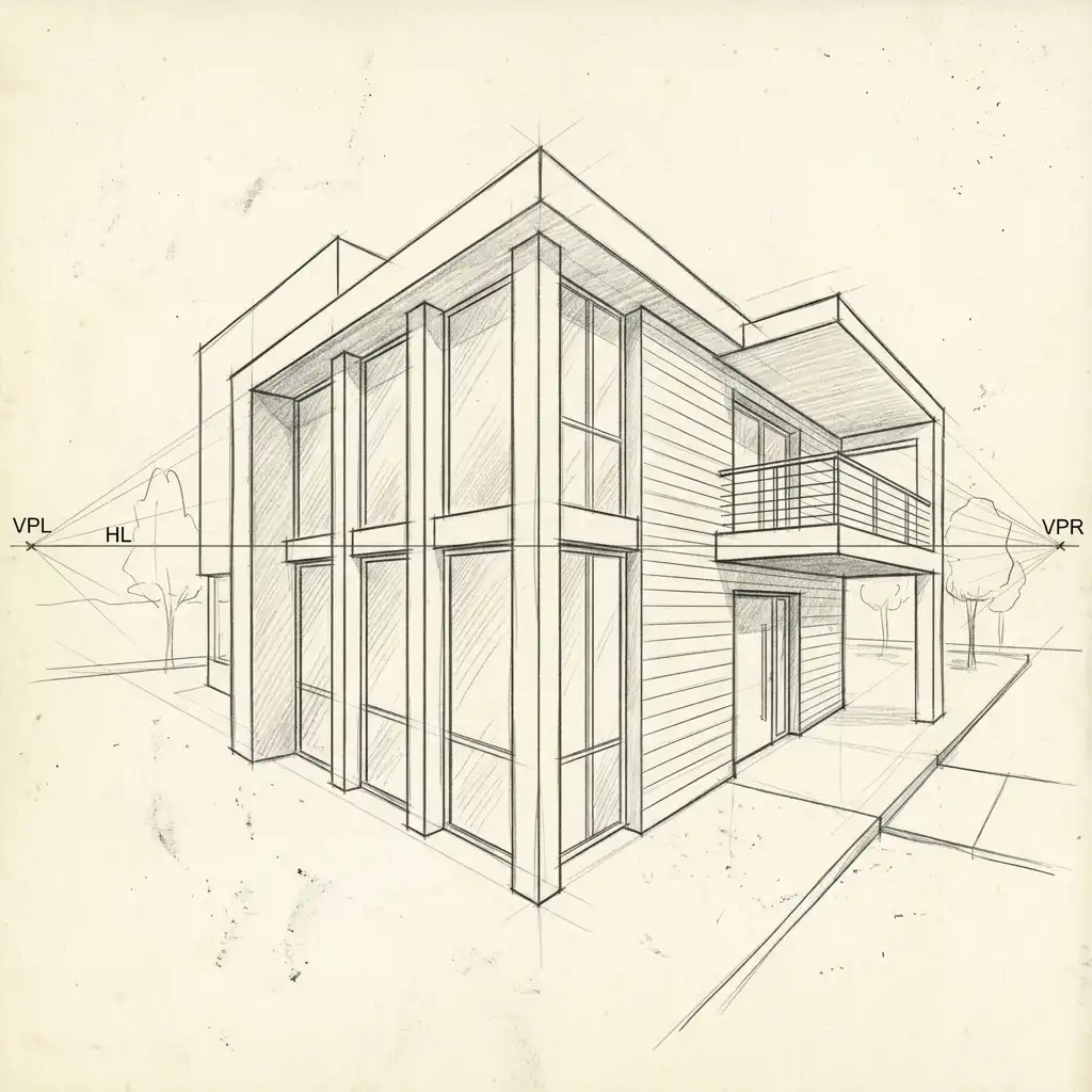
6. Perspective Sketch (Two-Point)
The two-point perspective sketch uses two vanishing points, typically placed at the left and right edges of the page. It is the standard method for showing building exteriors from a corner view, where both the front and side facades are visible.
In a two-point perspective, vertical lines remain straight, but all horizontal lines angle toward either the left or right vanishing point. This creates a more natural, dynamic view of a building than a flat elevation. Architects use two-point sketches to study how a building sits on its site, how shadows fall across multiple facades, and how the building relates to surrounding context.
Quick Tips
- Place the two vanishing points far apart — at least twice the width of your drawing — to avoid distortion.
- Establish the closest vertical corner of the building first, then draw lines from its top and bottom to both vanishing points.
- Add cast shadows by projecting lines from a single light source direction.
7. Axonometric Sketch
The axonometric sketch is a technical drawing that shows a building in three dimensions while keeping all lines parallel — no vanishing points. This makes it possible to measure directly from the drawing, unlike perspectives which distort scale with distance.
There are three types: isometric (angles equal at 30 degrees), dimetric (two angles equal), and trimetric (all angles different). The isometric sketch is most common: vertical lines remain vertical, while horizontal lines are drawn at 30 degrees above the horizontal. Architects use axonometric sketches to study how building systems (structure, circulation, enclosure) fit together in three dimensions.
Quick Tips
- Use a 30/60 triangle to maintain consistent angles across the entire drawing.
- Start with the footprint, then extrude vertical lines upward.
- Use different line weights to distinguish foreground from background elements.
8. Detail Sketch
The detail sketch zooms in to show how building materials connect, overlap, and terminate. Unlike the broader sketch types, details focus on a small area — typically a 30cm x 30cm to 60cm x 60cm section of the building — at a larger scale.
A typical detail sketch might show a window head flashing, a wall-to-floor transition, a railing connection, or a corner joint between two different materials. These sketches use heavy line weights for cut elements (like a timber joist or steel angle), medium lines for adjacent materials, and careful hatching to indicate different materials (brick, wood, concrete, insulation). Architects use detail sketches to solve construction problems on paper before they become problems on site.
Quick Tips
- Indicate material key with standard hatch patterns: diagonal lines for brick, circles for concrete, wavy lines for insulation.
- Draw a scale bar or note the scale (1:5, 1:10) directly on the sketch.
- Annotate each material with a leader line and label.

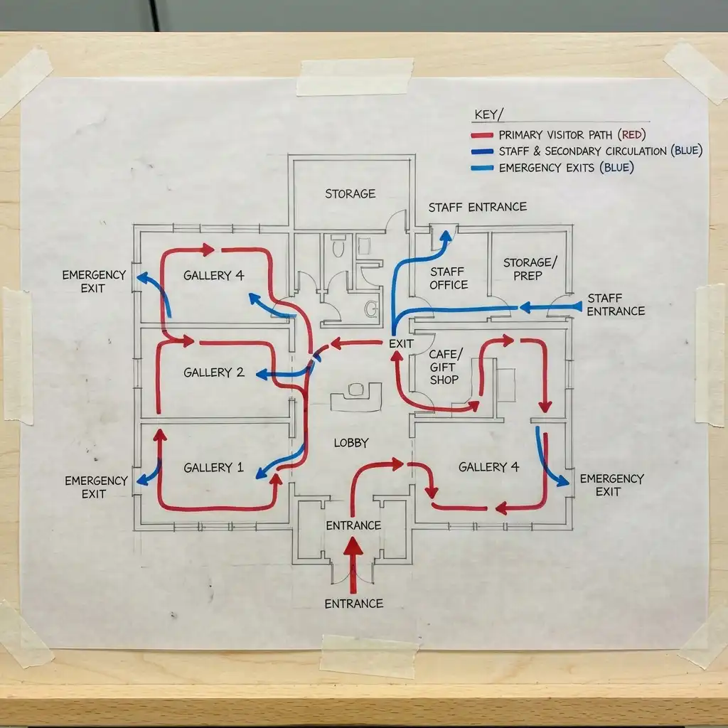
9. Circulation Diagram Sketch
The circulation diagram sketch ignores walls, windows, and materials entirely. Instead, it maps how people move through a building: entry points, paths, nodes (where paths cross), and destinations. It is the architect’s tool for testing whether a building flows logically.
These sketches use arrows to show direction, dotted lines to indicate secondary paths, and circles or squares to mark important spaces (entrance, stairs, elevators, exits). A good circulation diagram reveals problems that a floor plan might hide: a bottleneck at a narrow hallway, a confusing junction where paths cross, or a destination that requires walking through another space to reach.
Quick Tips
- Use red arrows for primary circulation and blue for secondary.
- Draw the building outline as a thin grey line — barely visible behind the arrows.
- Test your diagram by mentally walking from the entrance to each destination.
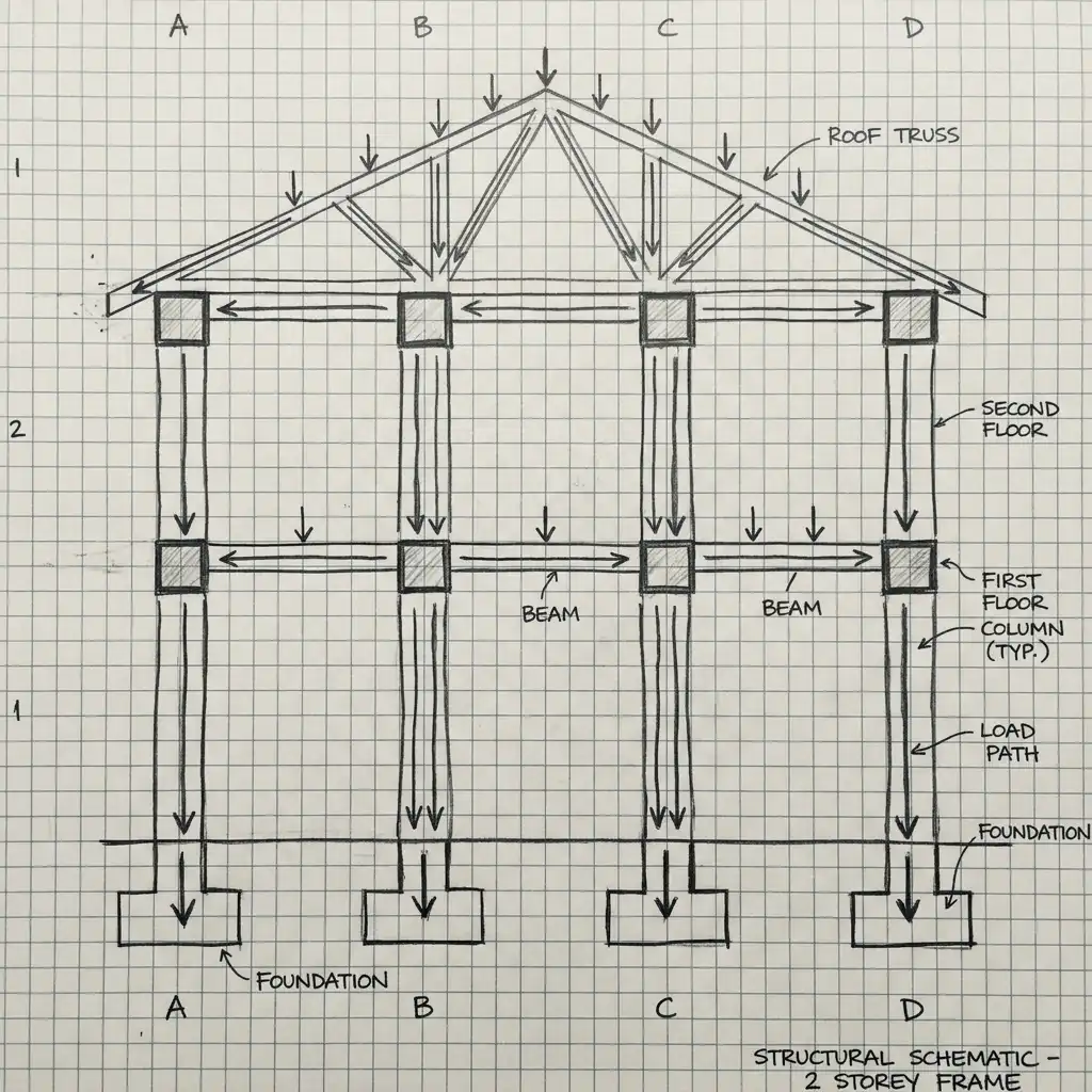
10. Structural Diagram Sketch
The structural diagram sketch strips away architecture to reveal the building’s bones: columns, beams, load-bearing walls, trusses, and foundations. It answers the question: what holds this building up?
Unlike detail sketches, structural diagrams are diagrammatic rather than literal. A column is shown as a simple square or circle, a beam as a single line, a truss as a repeating triangle pattern. Load paths are indicated with arrows showing how forces travel from roof to foundation. Architects use structural diagrams early in design to coordinate with engineers before detailed sizing begins.
Quick Tips
- Show columns at their centres, not their outer dimensions.
- Use dashed lines for beams hidden above or below the cut plane.
- Indicate the direction of floor joists or roof rafters with parallel lines.
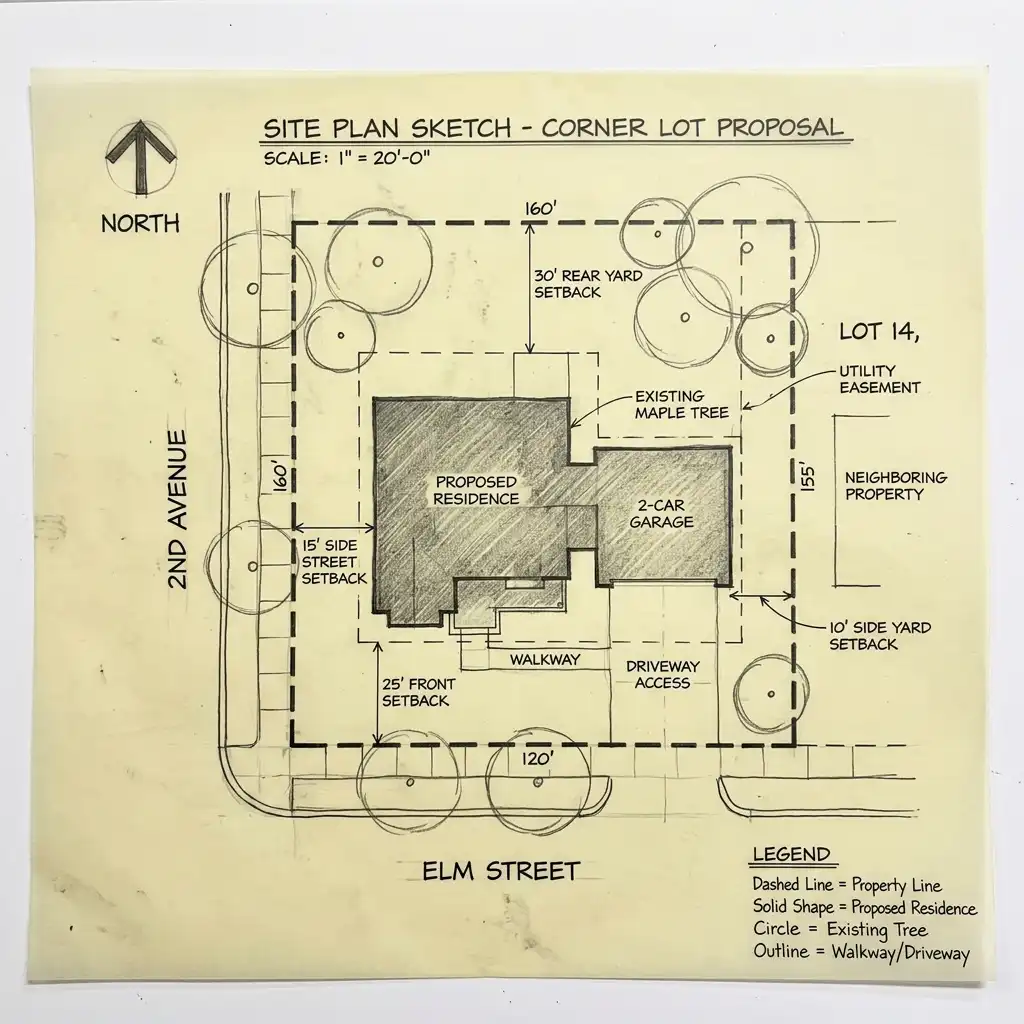
11. Site Plan Sketch
The site plan sketch looks down at a building and its surrounding land from above, similar to a floor plan but at a much smaller scale. It shows the building footprint, driveway, parking, walkways, landscape features, property lines, setbacks, and adjacent streets or neighbouring buildings.
A site plan sketch is the architect’s tool for understanding how a building relates to its context. It might show how morning sun hits the rear garden, how prevailing summer winds move across the patio, or how a new building sits relative to an old oak tree that must be preserved. Unlike interior sketches, site plans require accurate property lines and setback dimensions.
Quick Tips
- Draw property lines as thick dashed lines, building footprint as a solid shape.
- Indicate north with a large, clear north arrow.
- Show existing trees with circles representing their drip line (canopy edge).
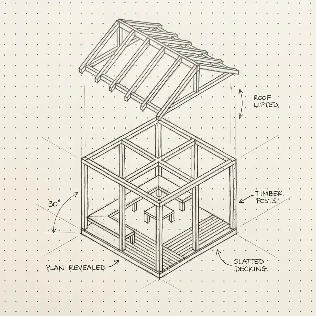
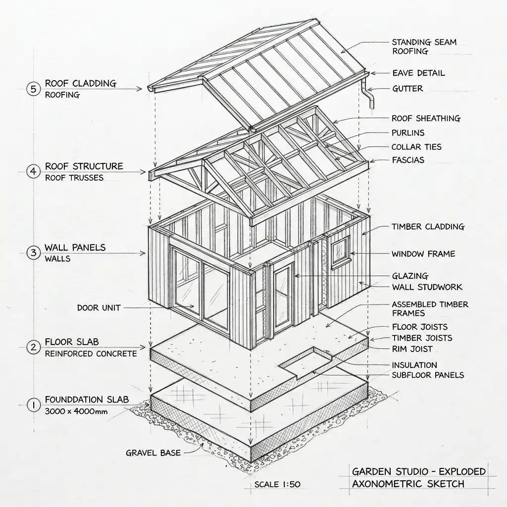
12. Exploded Axonometric Sketch
The exploded axonometric sketch takes a building or object apart layer by layer, spreading the components along a vertical or horizontal axis to show how they assemble. It is the most dramatic and informative of all sketch types.
A typical exploded axonometric of a small house might show, from bottom to top: the foundation slab, the first floor structure, the wall framing and windows, the second floor, the roof structure, and finally the roof cladding — each layer floating slightly above the one below. This sketch type is invaluable for explaining complex assemblies to clients, builders, or students.
Quick Tips
- Choose a consistent explosion direction — vertical (upward) is most common for buildings.
- Keep the spacing between layers equal so the drawing remains readable.
- Use leader lines with small circles to connect exploded components back to their original positions.
Final Thoughts
Architecture sketches are not just tools — they are a way of thinking. Each sketch type serves a different purpose, from the loose conceptual massing study to the precise exploded axonometric. The best architects move fluidly between these types, choosing the right sketch for the question they are trying to answer.
Whether you are a student building your skills or a professional refining your process, mastering these 12 sketch types will make you a clearer thinker and a more effective communicator. A good sketch is worth a thousand words — and sometimes worth more than a hundred digital renderings.
IMPORTANT DISCLAIMER: All sketches described in this post are for educational and design inspiration purposes only. Construction drawings, permit sets, and detailed architectural documentation require precise dimensioning, professional standards compliance, and review by licensed professionals. Always consult registered architects, structural engineers, and local building authorities before proceeding with any construction project.